Wiring Diagrams
Visual Wiring Diagram
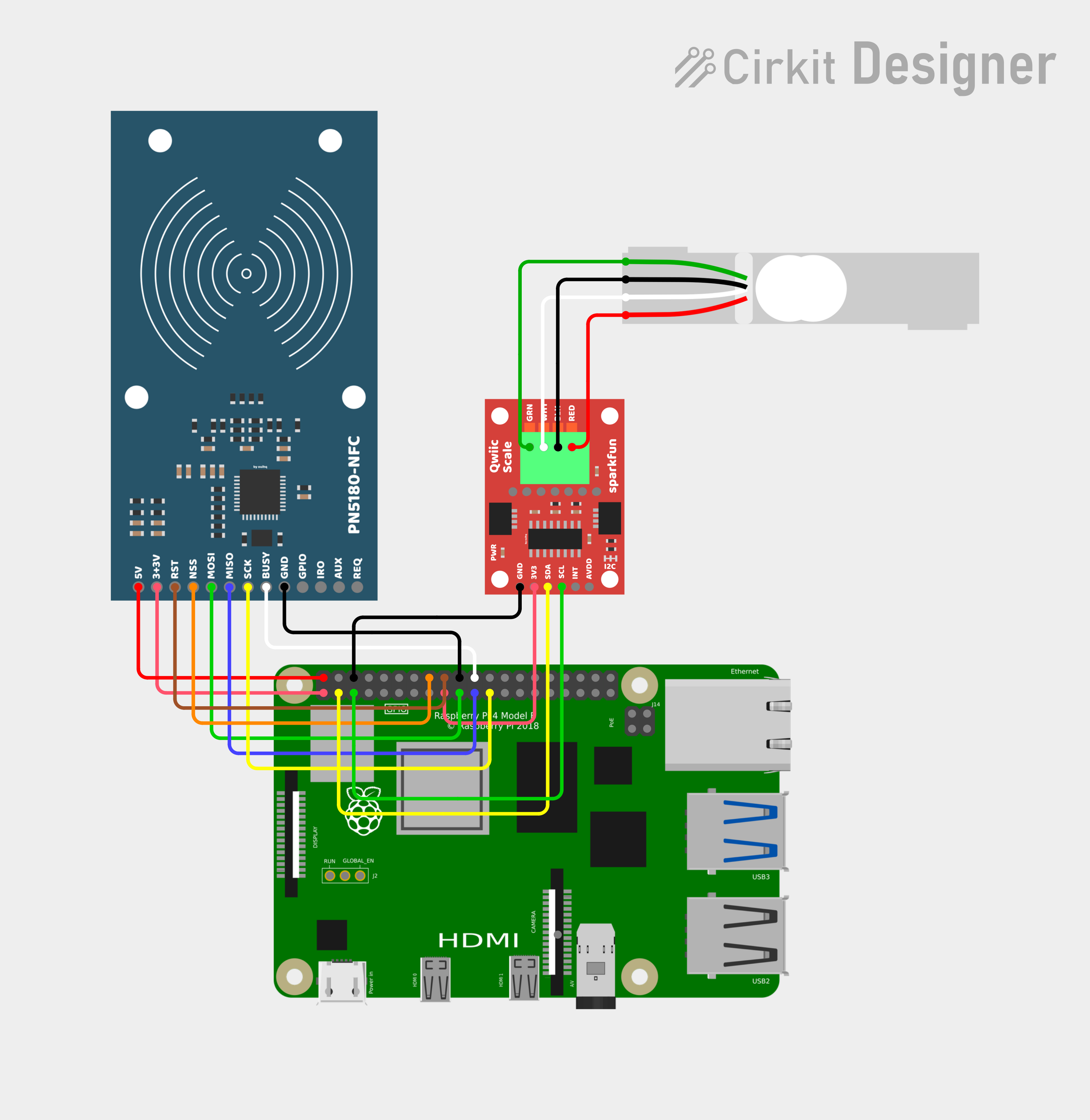
Below is the Fritzing-style wiring overview showing all SpoolBuddy components connected to a Raspberry Pi 4.
 by ouihq
 Diagram created with Cirkit Designer. Components: Raspberry Pi 4 Model B, PN5180-NFC reader (SPI), SparkFun Qwiic Scale NAU7802 (I2C), 5 kg single-point load cell.
Verify GPIO pins for your Pi model
All diagrams on this page are based on the Raspberry Pi 4 Model B. GPIO pin numbers and physical header positions are consistent across most Pi models, but always cross-reference against the pinout for your specific board at pinout.xyz before wiring. Some combinations (e.g. Pi 5, Pi Zero, CM4) may require adjustments.
PN5180 NFC Reader — Pi GPIO Wiring
The PN5180 communicates over SPI0 with a manual chip-select on GPIO23.
Dual voltage requirement
The PN5180 requires both 5 V and 3.3 V connections. Do not connect 5 V to the 3V3 pin — this will damage the module.
| PN5180 Pin | Direction | Pi GPIO | Pi Physical Pin | Wire Color | Notes |
|---|---|---|---|---|---|
| 5V | ← | — | Pin 2 | Red | 5 V power rail |
| 3V3 | ← | — | Pin 1 | Red | 3.3 V power rail |
| RST | ← | GPIO24 | Pin 18 | Brown | Hardware reset |
| NSS | ← | GPIO23 | Pin 16 | Orange | Manual chip-select (dtoverlay=spi0-0cs) |
| MOSI | ← | GPIO10 | Pin 19 | Green | SPI0 MOSI |
| MISO | → | GPIO9 | Pin 21 | Blue | SPI0 MISO |
| SCK | ← | GPIO11 | Pin 23 | Yellow | SPI0 SCLK |
| BUSY | → | GPIO25 | Pin 22 | White | Busy/wait signal |
| GND | — | — | Pin 20 | Black | Ground |
| GPIO | — | — | — | — | Not connected |
| IRQ | → | GPIO17 | Pin 11 | Purple | Interrupt (optional) |
| AUX | — | — | — | — | Not connected |
| REQ | — | — | — | — | Not connected |
ASCII — PN5180 to Pi
  PN5180-NFC                            Raspberry Pi 4 GPIO Header
  ┌──────────┐                         ┌─────────────────────────┐
  │          │                         │  (active-low CS)        │
  │  5V    ──┼── Red ───────────────── │── Pin  2  (5V)          │
  │  3V3   ──┼── Red ───────────────── │── Pin  1  (3V3)         │
  │  RST   ──┼── Brown ─────────────── │── Pin 18  (GPIO24)      │
  │  NSS   ──┼── Orange ────────────── │── Pin 16  (GPIO23)      │
  │  MOSI  ──┼── Green ─────────────── │── Pin 19  (GPIO10)      │
  │  MISO  ──┼── Blue ──────────────── │── Pin 21  (GPIO9)       │
  │  SCK   ──┼── Yellow ────────────── │── Pin 23  (GPIO11)      │
  │  BUSY  ──┼── White ─────────────── │── Pin 22  (GPIO25)      │
  │  GND   ──┼── Black ─────────────── │── Pin 20  (GND)         │
  │  GPIO  ──┼   (NC)                  │                         │
  │  IRQ   ──┼   (NC)                  │                         │
  │  AUX   ──┼   (NC)                  │                         │
  │  REQ   ──┼   (NC)                  │                         │
  └──────────┘                         └─────────────────────────┘
Manual chip-select
SpoolBuddy uses dtoverlay=spi0-0cs in /boot/firmware/config.txt to disable the kernel's automatic CS so the daemon can manually toggle GPIO23 to meet PN5180 timing requirements.
NAU7802 Scale ADC — Pi I2C Wiring
The SparkFun Qwiic NAU7802 communicates over I2C bus 1 at address 0x2A.
I2C bus 1
SpoolBuddy uses /dev/i2c-1 (GPIO2/GPIO3). Make sure I2C-1 is enabled in your boot config.
| NAU7802 Pin | Direction | Pi GPIO | Pi Physical Pin | Wire Color | Notes |
|---|---|---|---|---|---|
| 3V3 | ← | — | Pin 17 | Red | 3.3 V power |
| GND | — | — | Pin 6 | Black | Ground |
| SDA | ↔ | GPIO2 | Pin 3 | Yellow | I2C-1 data |
| SCL | ← | GPIO3 | Pin 5 | Green | I2C-1 clock |
| INT | → | — | — | — | Not connected |
ASCII — NAU7802 to Pi
  SparkFun Qwiic NAU7802                 Raspberry Pi 4 GPIO Header
  ┌───────────────────┐                 ┌──────────────────────────┐
  │                   │                 │                          │
  │  3V3  ────────── ─┼── Red ───────── │── Pin 17  (3V3)          │
  │  GND  ────────── ─┼── Black ─────── │── Pin  6  (GND)          │
  │  SDA  ────────── ─┼── Yellow ────── │── Pin  3  (GPIO2 / SDA1) │
  │  SCL  ────────── ─┼── Green ─────── │── Pin  5  (GPIO3 / SCL1) │
  │  INT  ────────── ─┼   (NC)          │                          │
  └───────────────────┘                 └──────────────────────────┘
Load Cell — NAU7802 Wiring
A standard 4-wire load cell connects to the screw terminals on the SparkFun Qwiic NAU7802 board.
| Load Cell Wire | Color | NAU7802 Terminal | Function |
|---|---|---|---|
| E+ | Red | E+ | Excitation positive |
| E− | Black | E− | Excitation negative |
| A+ (S+) | Green | A+ | Signal positive |
| A− (S−) | White | A− | Signal negative |
ASCII — Load Cell to NAU7802
  Load Cell (5 kg)                    SparkFun Qwiic NAU7802
  ┌──────────────┐                     ┌───────────────────┐
  │              │                     │  Screw Terminals  │
  │  RED   (E+) ─┼── Red ───────────── │── E+              │
  │  BLACK (E−) ─┼── Black ─────────── │── E−              │
  │  GREEN (A+) ─┼── Green ─────────── │── A+              │
  │  WHITE (A−) ─┼── White ─────────── │── A−              │
  │              │                     │                   │
  └──────────────┘                     └───────────────────┘
Wire color convention
Most single-point load cells follow the color convention above. If your load cell uses different colors, refer to its datasheet. The key is matching excitation (E+/E−) and signal (A+/A−) correctly.
USB-C Power — Pi Power Wiring
An angled USB-C connector plugs into the Pi's USB-C port. The cable exits through the cutout on the back of the case, where a standard USB-C power supply can be connected.
Assembly Hardware
Cable Lengths
| Connection | Approximate Length |
|---|---|
| PN5180 NFC → Pi GPIO | ~25 cm |
| NAU7802 Scale → Pi GPIO | ~15 cm |
| Load cell → NAU7802 | Measure to fit |
GPIO Crimp Connectors
Wires to the Pi GPIO header use HARWIN M20 series 2.54 mm pitch connectors.
| Part | Description |
|---|---|
| M20-1160042 | Female crimp contact |
| M20-1070300 | 3-way housing (other pin counts available in the M20-107 range) |
Crimp tools:
- HARWIN Z20-320 — dedicated tool, produces reliable results but is expensive
- Generic crimp tool with SN-2549 jaw — a more affordable alternative that works well for M20 contacts
- Wire stripper — for stripping insulation before crimping
- Wire cutters — for cutting wires to length
Pi GPIO Connection Options
Several connector types can be used to connect wires to the Pi's GPIO pins:
- HARWIN M20 crimped connectors (recommended) — reliable contact, clean fit on the 2.54 mm GPIO pins
- Dupont connectors — widely available and easy to use, but can suffer from loose contact with the GPIO pins, causing signal quality issues or intermittent errors; use a multimeter in continuity mode to verify each connection before closing the case
- Other 2.54 mm pitch connectors — any compatible 2.54 mm female connector housing will fit the Pi's GPIO pins
- Soldering directly to the Pi — possible but very difficult; the GPIO pins are closely spaced and a bad joint or solder bridge can permanently damage the board; only attempt this if you are very confident in your soldering skills
Soldering to Modules
Soldering wires directly to the PN5180 and NAU7802 module pads is straightforward and gives a reliable, permanent connection. This is the recommended approach for the module side of each harness.
Full System ASCII Wiring Diagram
     Raspberry Pi 4B                    PN5180 NFC (SPI0)
 ┌─────────────────────┐              ┌──────────────────┐
 │  Pin 1  (3V3) ──────┼──────────────┤ 3V3   [red]      │
 │  Pin 2  (5V) ───────┼──────────────┤ 5V    [red]      │
 │  Pin 16 (GPIO23) ───┼──────────────┤ NSS   [orange]   │
 │  Pin 18 (GPIO24) ───┼──────────────┤ RST   [brown]    │
 │  Pin 19 (GPIO10) ───┼──────────────┤ MOSI  [green]    │
 │  Pin 20 (GND) ──────┼──────────────┤ GND   [black]    │
 │  Pin 21 (GPIO9) ────┼──────────────┤ MISO  [blue]     │
 │  Pin 22 (GPIO25) ───┼──────────────┤ BUSY  [white]    │
 │  Pin 23 (GPIO11) ───┼──────────────┤ SCK   [yellow]   │
 │                     │              └──────────────────┘
 │  Pin 3  (GPIO2) ────┼──────────┐
 │  Pin 5  (GPIO3) ────┼────────┐ │   NAU7802 Scale (I2C-1)
 │  Pin 6  (GND) ──────┼──────┐ │ │   ┌──────────────────┐
 │  Pin 17 (3V3) ──────┼────┐ │ │ │   │                  │
 │                     │    └─┼─┼─┼───┤ 3V3  [red]       │
 │                     │      └─┼─┼───┤ GND  [black]     │
 │                     │        └─┼───┤ SCL  [green]     │
 │                     │          └───┤ SDA  [yellow]    │
 └─────────────────────┘              │                  │
                                      │  E+  ────────────┼── RED   (load cell)
                                      │  E−  ────────────┼── BLACK (load cell)
                                      │  A+  ────────────┼── GREEN (load cell)
                                      │  A−  ────────────┼── WHITE (load cell)
                                      └──────────────────┘
Required Boot Config
Add the following to /boot/firmware/config.txt (if you use the SpoolBuddy installer, it will handle this step automatically):
# Enable SPI with no automatic CS (manual GPIO23 chip-select)
dtparam=spi=on
dtoverlay=spi0-0cs

# Enable I2C bus 1 for NAU7802 (GPIO2/GPIO3)
dtparam=i2c_arm=on
After editing, reboot:
Post-Wiring Verification
After wiring all components, verify with these checks:
# Confirm SPI devices are present
ls /dev/spidev0.*
# Expected: /dev/spidev0.0

# Confirm I2C bus 1 is present
ls /dev/i2c-1
# Expected: /dev/i2c-1

# Scan I2C bus 1 for NAU7802 at address 0x2A
sudo i2cdetect -y 1
# Expected: "2a" appears in the grid
Hardware detected?
If SPI and I2C devices appear and the NAU7802 shows at 0x2A, your wiring is correct. Proceed to Assembly to build the case, then Installation to set up the software.
Troubleshooting wiring issues
If diagnostics fail, double-check these common issues:
- PN5180 not detected: Verify 5 V is connected. Check MOSI/MISO aren't swapped. Confirm
dtoverlay=spi0-0csis in boot config. - NAU7802 not at 0x2A: Make sure you're on I2C bus 1 (GPIO2/GPIO3, pins ⅗). Check
dtparam=i2c_arm=onis in boot config. - Scale reads zero: Check load cell wiring (E+/E−/A+/A−) and confirm the NAU7802 is powered on Pin 17 (3V3) and Pin 6 (GND).
- Unstable NFC reads: Keep NFC wiring short. Long or loose jumper wires cause signal degradation.
Related Pages
- Hardware Requirements — Component overview and build notes
- Materials Required — Full bill of materials with shop links
- Installation — Software setup after wiring
- Configuration — Daemon and kiosk settings